Description
A door sensor is an electronic circuit arrangement with two parts - one piece secured to the door and the other piece secured to the frame around the door. Each piece has a magnet. When the door is closed, the magnets are in contact. The electricity can flow through the magnets, completing the circuit. However, when the door is open, the magnets are apart, breaking the circuit. This is the basic working principle of a door sensor.
Block description
This block can be used to receive digital inputs (high or low) from a door sensor circuit connected to any of the ports S1, S2, S3.
Hardware interface
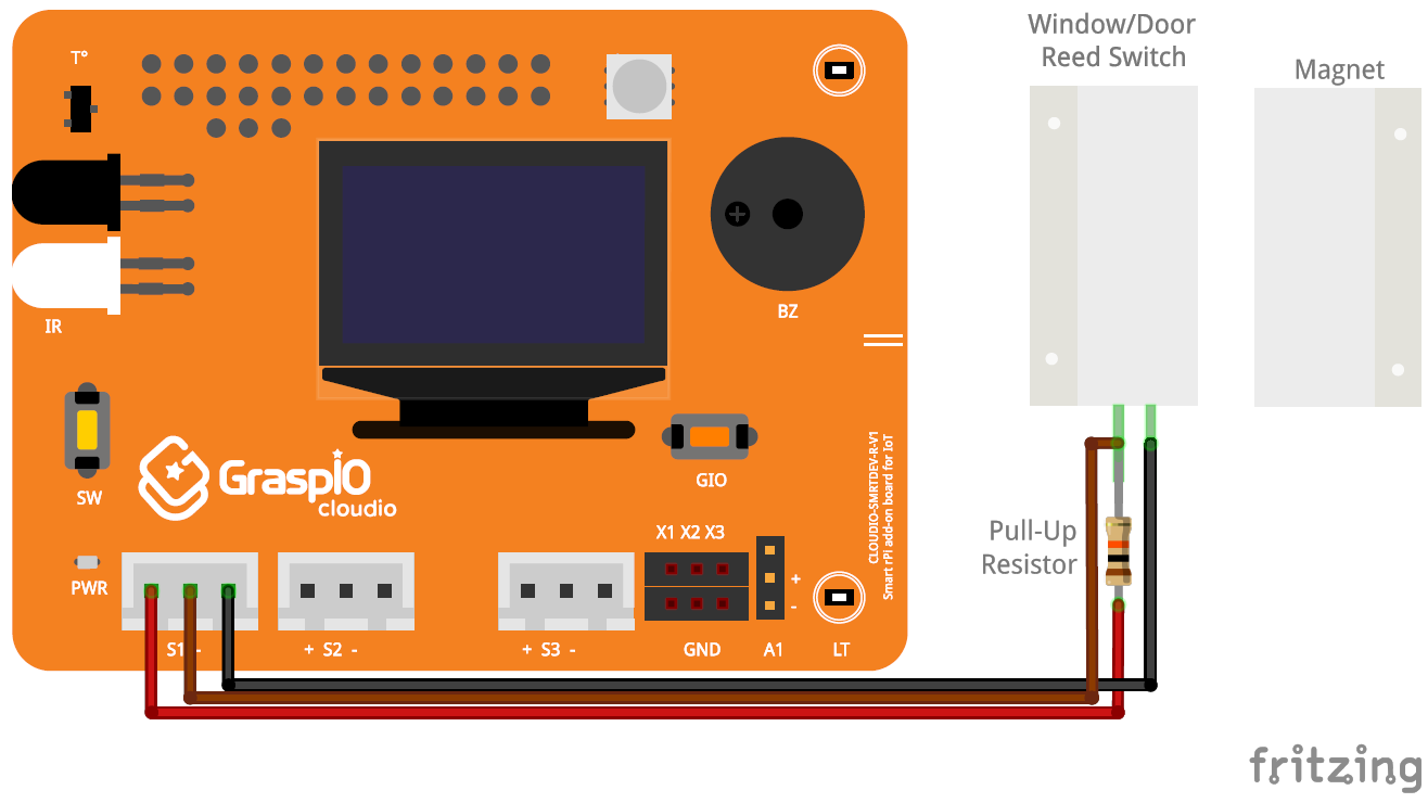
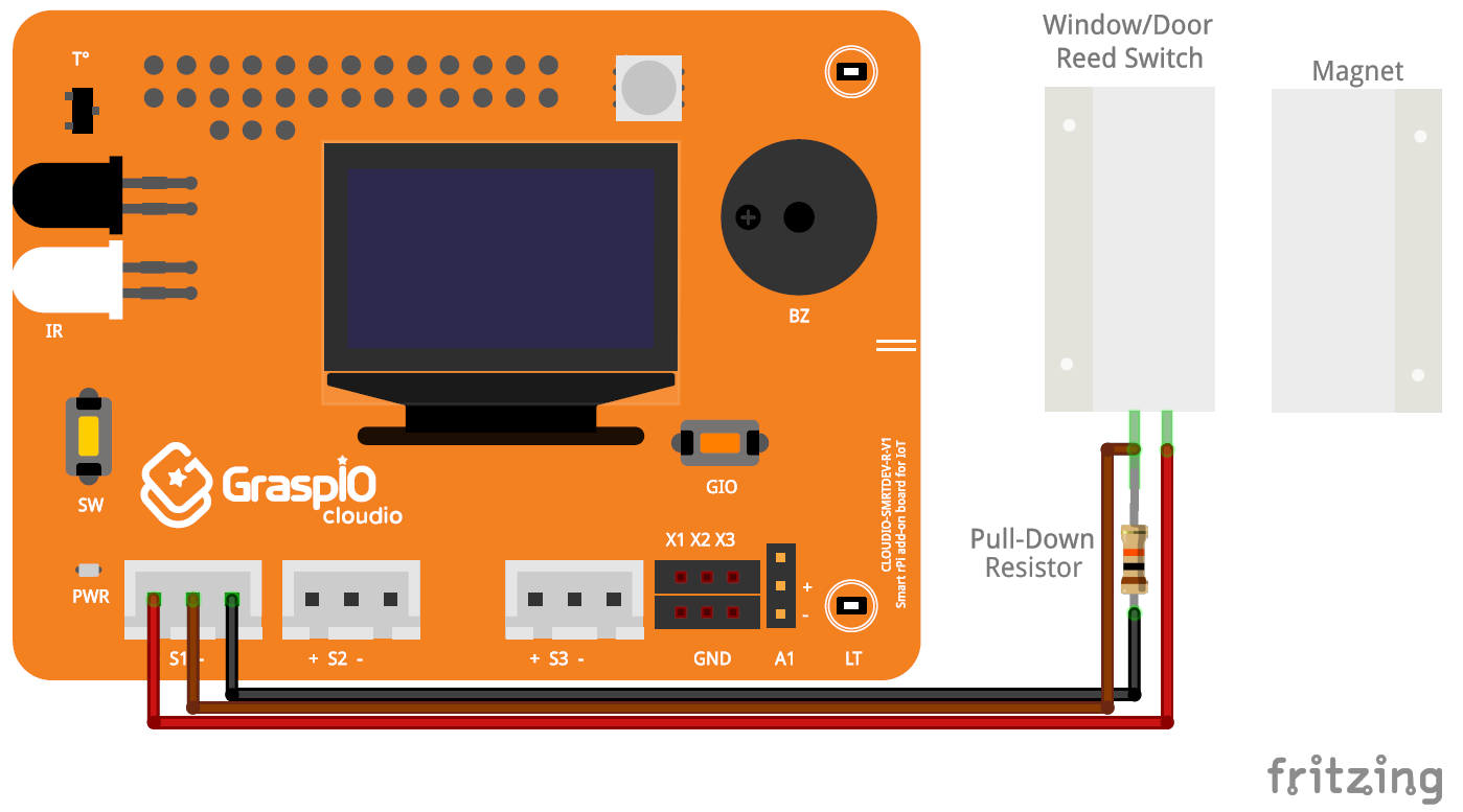
Connecting an external Door sensor
Note: While connecting an external sensor to the Cloudio board, care must be taken to match the polarities of the sensor with that of the port (S1/S2/S3) that it is being connected to.
Using a pull-up resistor circuit


Using a pull-down resistor circuit


App interface and usage
Port selection:
Here, you can select the port the Door sensor is connected to.
• S1/S2/S3 (The port the Door sensor is connected to)
Operator:
Here, you can select the operator to be used while comparing the sensor reading against threshold values of High or Low.
State:
You can set the threshold state to be compared against the value received from the sensor.
You can use the Read option to read/receive real-time values from the port selected.
After you set the parameters for the block, you can press Done to confirm and save your changes.
Guidelines
While creating projects that use external circuits for Door sensors, the High and Low states may actually depend on the design of the circuit (whether it used a pull-up resistor or a pull-down one)