Description
A digital switch refers to a push button which is ON (or OFF) when pressed, and OFF (or ON) when not. When the switch is pressed, two points in the circuit are connected, and the circuit is completed. It is to be noted, however, that a push button is ON (or OFF) only until the user presses the switch.
Block description:
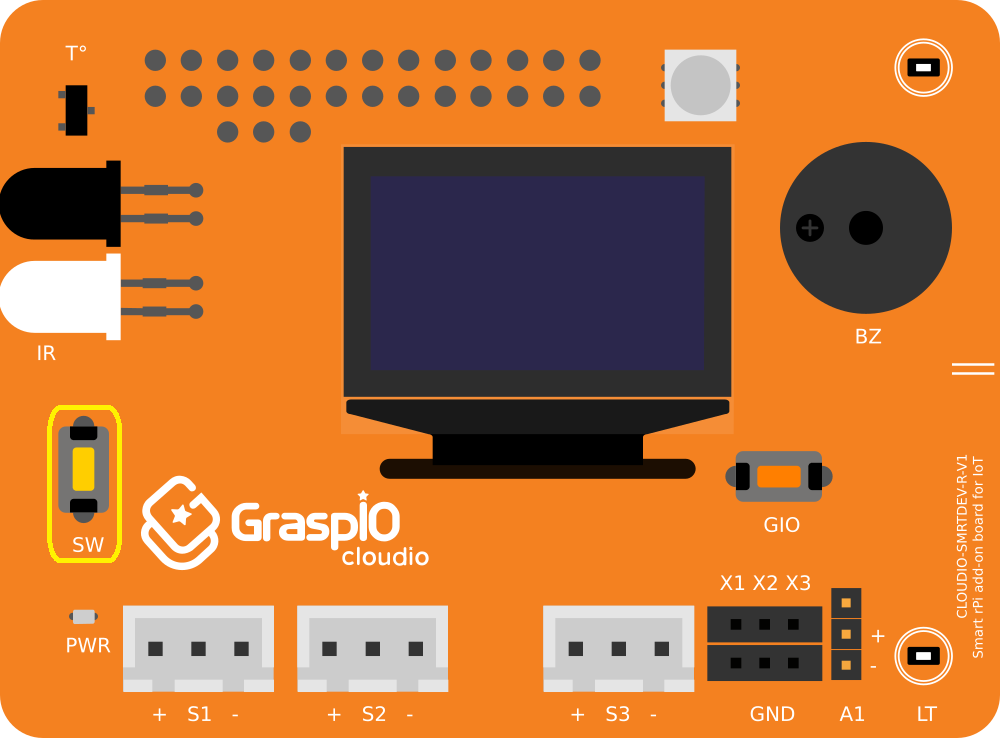
This block can be used in digital mode to receive the states (High or Low) inputs from a digital switch. The sensor can be the on-board tactile switch (SW), or an external sensor connected to any of the ports S1, S2, S3.
Hardware interface
On-board Switch
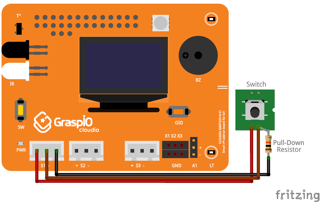
Connecting an external switch
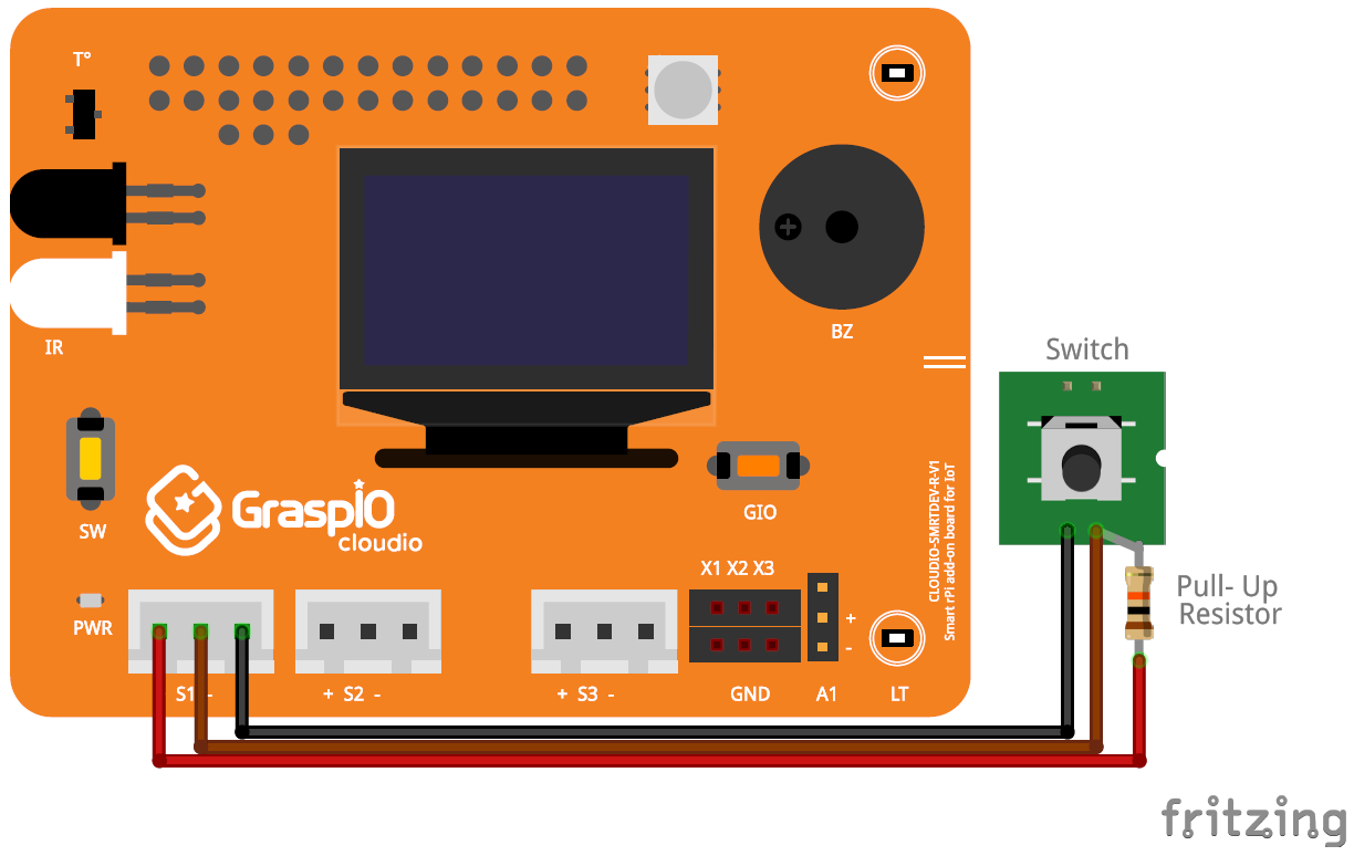
Note: While connecting an external sensor to the Cloudio board, care must be taken to match the polarities of the sensor with that of the port (S1/S2/S3) that it is being connected to.
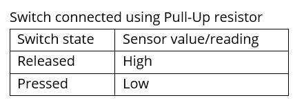
Switch connected using Pull-Up resistor
Switch connected using Pull-Down resistor

App interface and usage
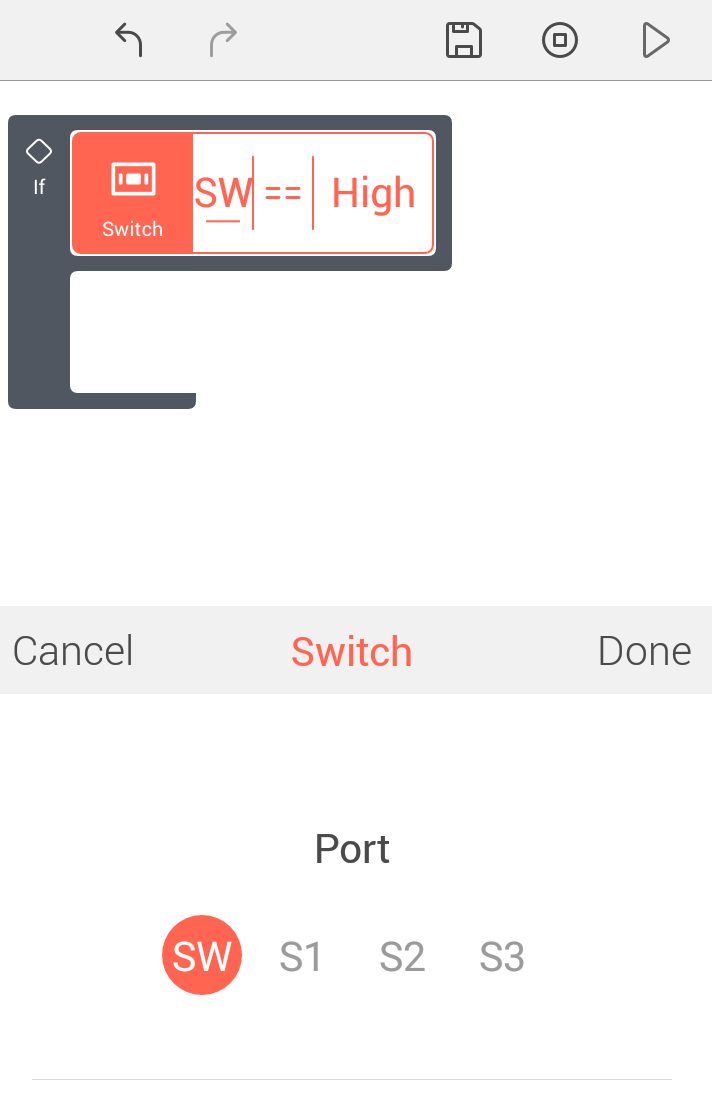
Port:
Here, you can select the port the Switch is connected to.
• SW (if you’re using the on-board switch SW),
or
• S1/S2/S3 (if you’re using an external switch connected to either of the 3 ports)
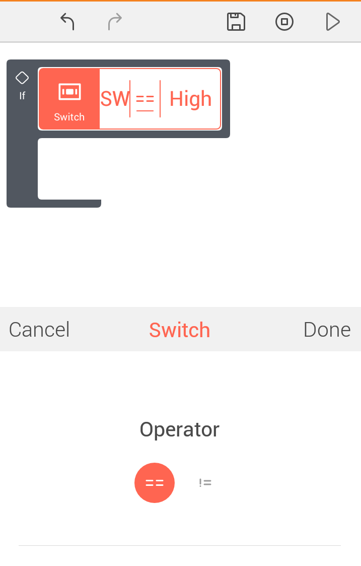
Operator:
Here, you can select the operator to be used while comparing the switch reading against threshold values of High or Low.
State:
You can set the threshold state to be compared against the value received from the Switch.
You can use the Read option to read/receive real-time values from the port selected. (Refer Read section)
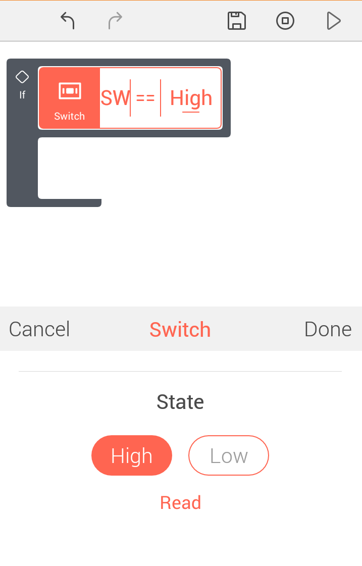
After you set the parameters for the block, you can press Done to confirm and save your changes.
Guidelines
While creating projects that use switches, please make sure you account for switch debouncing. i.e., a switch may continue to stay pressed for a while after it is pressed. For example, if your project needs to count the number of times a switch is pressed, make sure to write your code such that change in state from Low to High and back to Low is considered one instance of the switch being pressed.
Examples
Note: These are just code snippets to explain the working of the block. In this case, this code will be executed once and at the time of uploading the code.
You will need to use this snippet inside a loop infinitely block if you want this code to run on the board for the entire duration that the board is on.
-
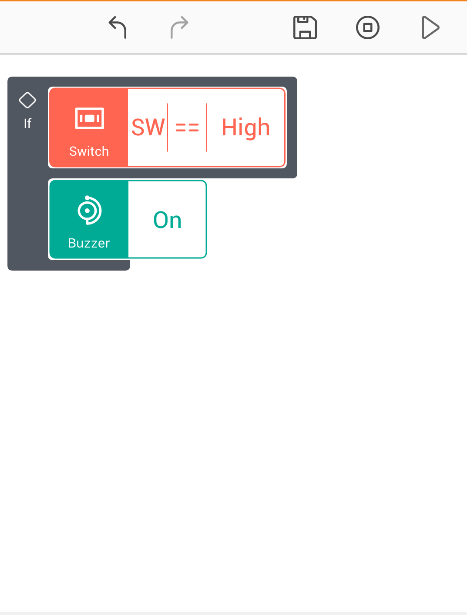
The below project snippet uses the on-board Switch SW to notify you when the Switch is pressed. It turns the Buzzer ON if SW is pressed (High).
(Note: In this example snippet, the buzzer will continue to remain ON even after the switch is released)
-
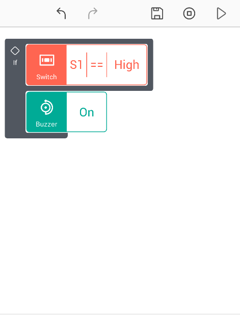
The below project snippet uses an external switch. It turns the Buzzer ON if the reading from the Switch circuit is High.
(Note: The buzzer will continue to remain ON even after the reading from the Switch has turned OFF, or its reading changed)
-
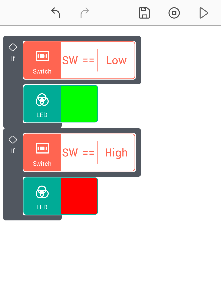
The below project snippet uses the on-board Switch SW to visually notify you when the Switch is pressed. It turns the LED Red if SW is pressed (High), while the LED is green when the switch is not pressed.
